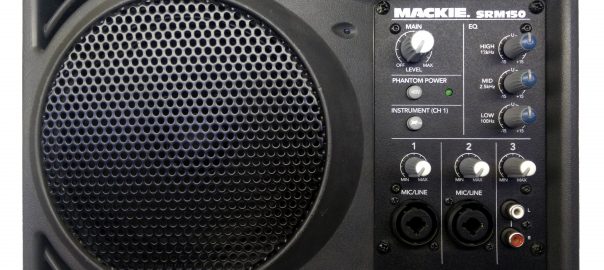
I received two Mackie SRM150 amplifiers that had the same problem: both powered on but did not reproduce any sound apart from some louder than normal hiss and a very noticeable pop when turning up the volume. The problem on both units turned out to be a defective linear regulator component on the preamp/mixer board. Read further if you want to learn more about the repair…
Problem
- When powering the SRM150 speaker, the blue power LED lights up and you hear a noticeable hiss coming out of the speaker, even with the MAIN level completely turned down.
- Turning the MAIN level above 5 makes a loud popping sound and the cone of the speaker visibly travels backwards very hard.
- No output from the speaker when feeding in a signal.
- When turning off the speaker with the POWER switch at the back, it makes a loud popping noise.
Disassembly
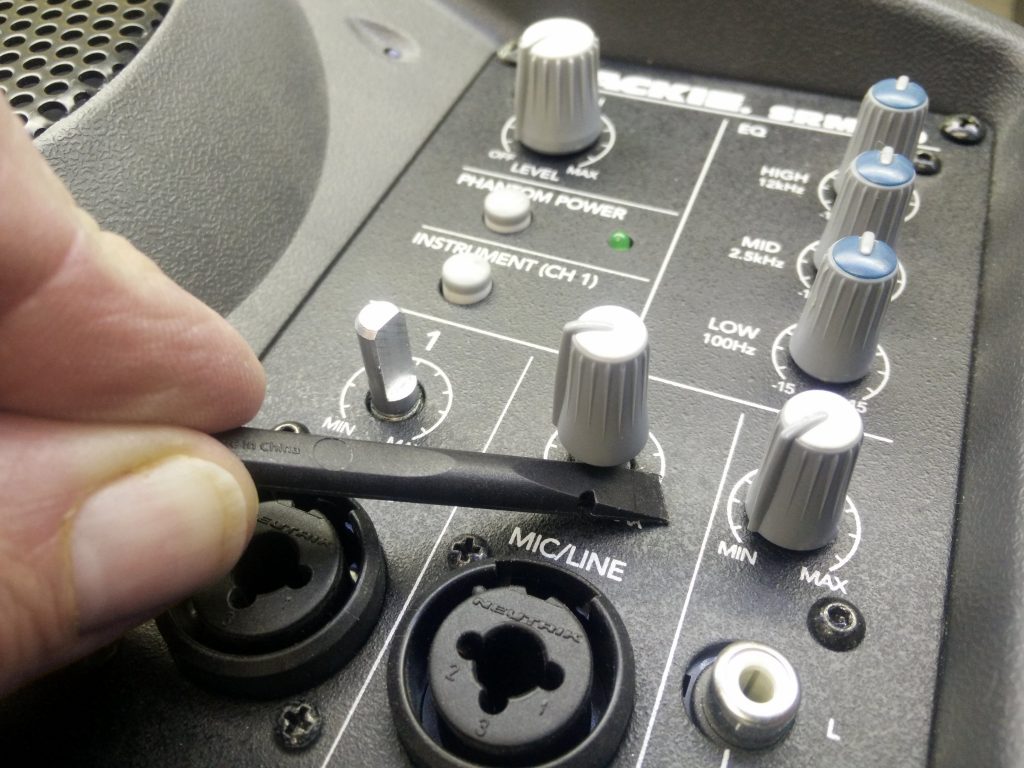
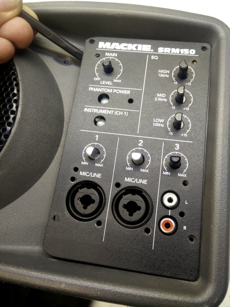
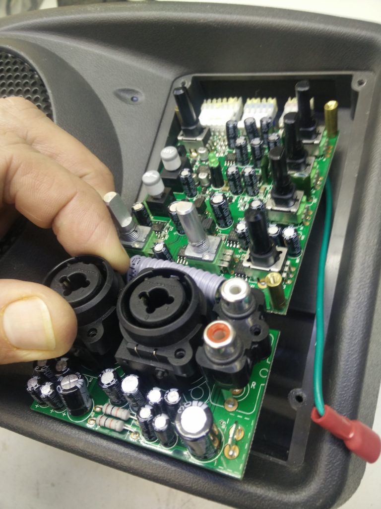
- Start with removing the six volume and EQ knobs by pulling them off. Pull them firmly, but do no wiggle them. If needed, wedge them loose with a plastic spudger.
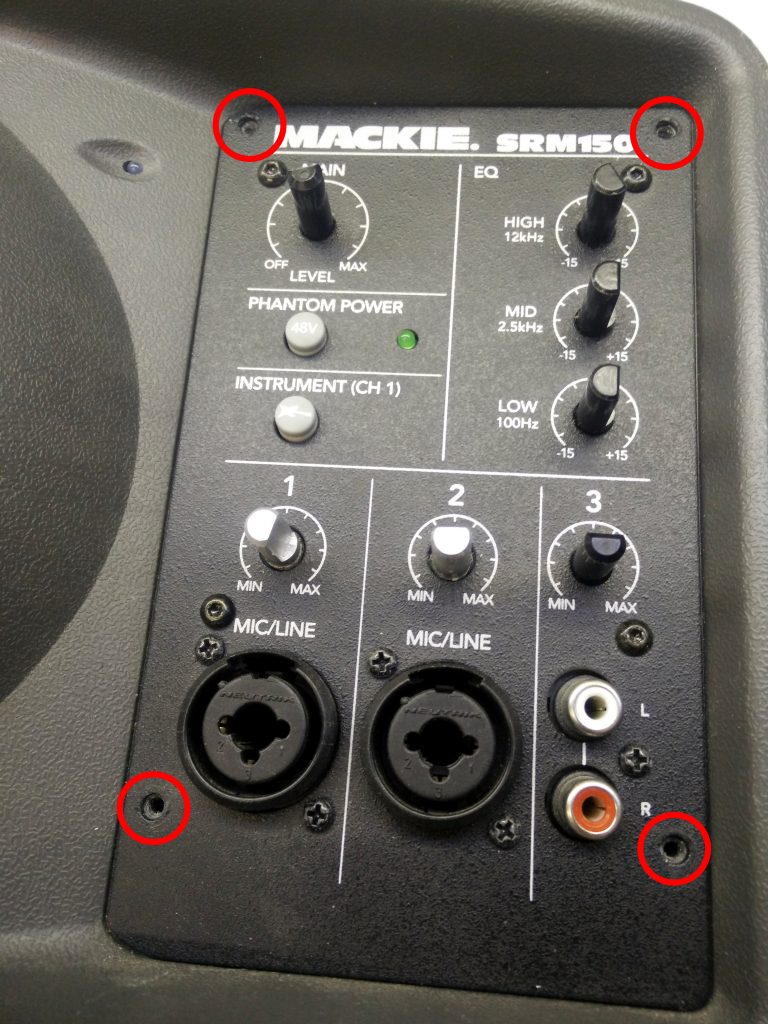
- Remove the four screws in the outer corners of the mixing panel with a Phillips #1 screwdriver.
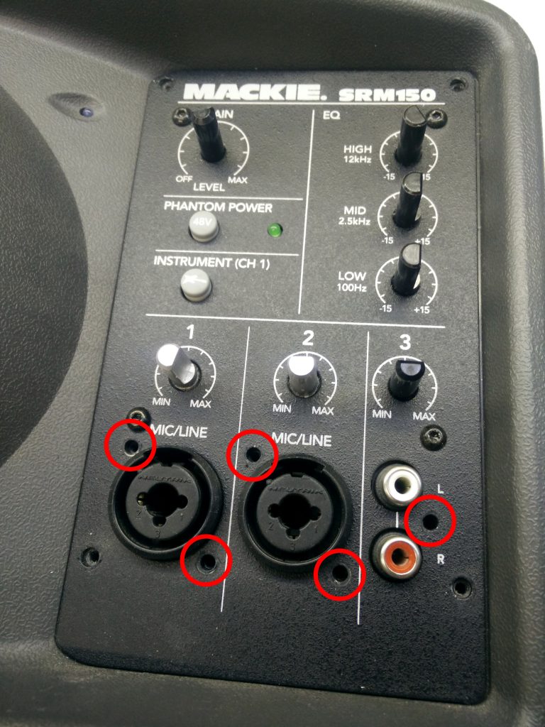
- Remove the five screws near the bottom surrounding the three inputs with a Phillips #0 screwdriver.
- Remove the four remaining machine screws with a Torx T8 screwdriver.
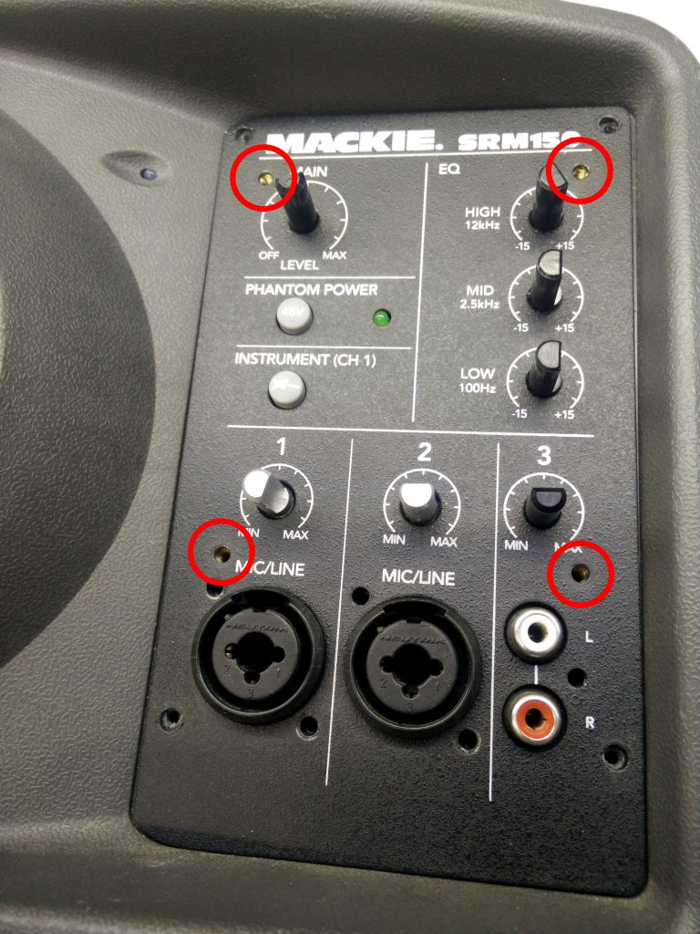
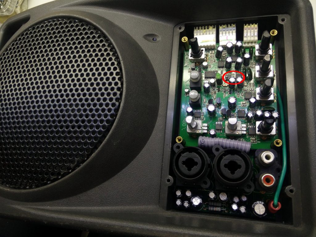
- Since there are no screws left, you should be able to lift the metal face plate of the mixing panel, exposing the printed circuit board that holds the components of the mixer.
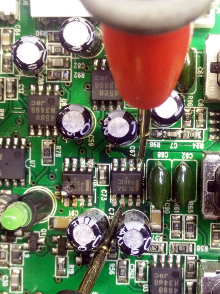
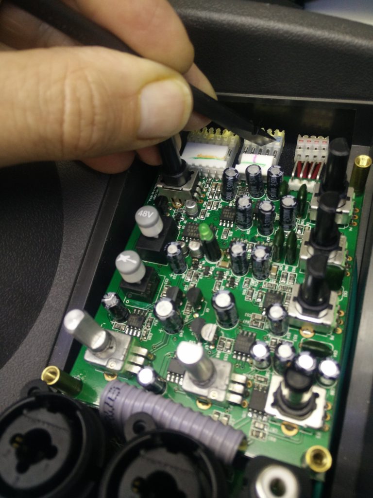
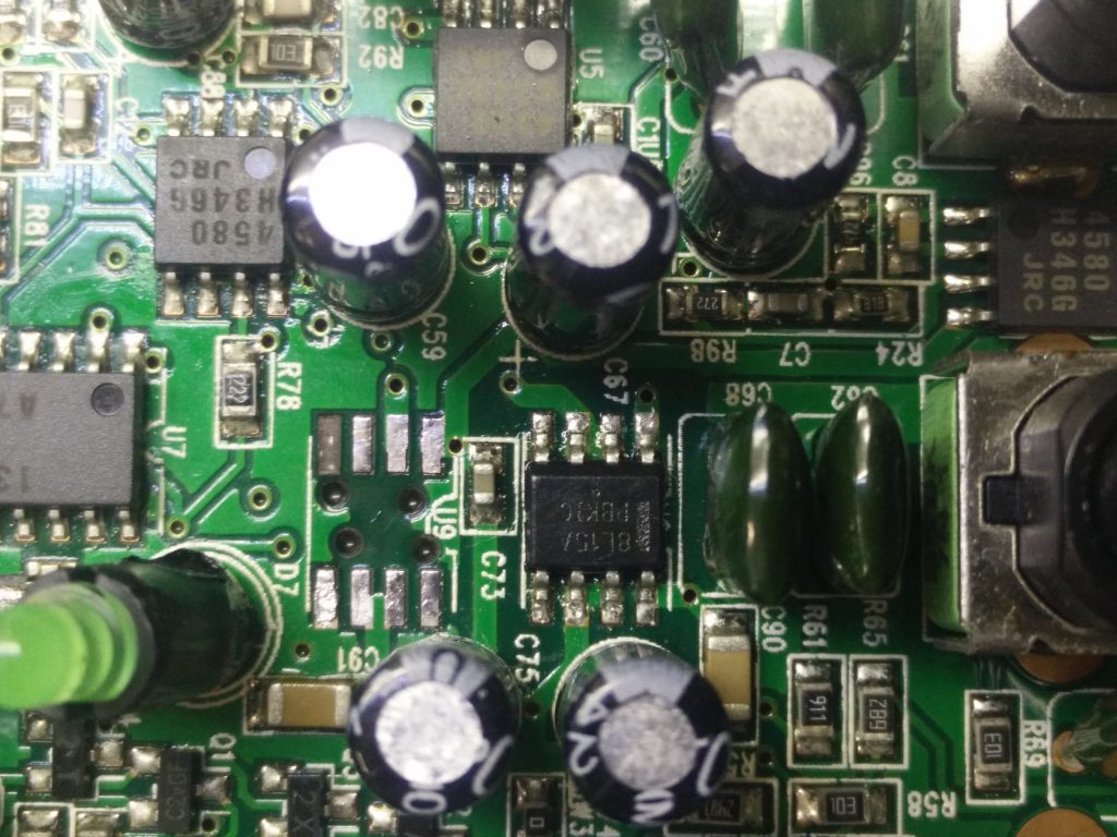
- We will be replacing the integrated circuits marked 9L15A or 8L15A, depending on which one is defective.
Diagnosis
- Measure the voltage on the two right pins of J4, you should get about 25V.
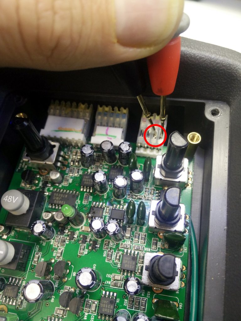
- Measure the voltage on the two center pins of J4, you should get about 25V.
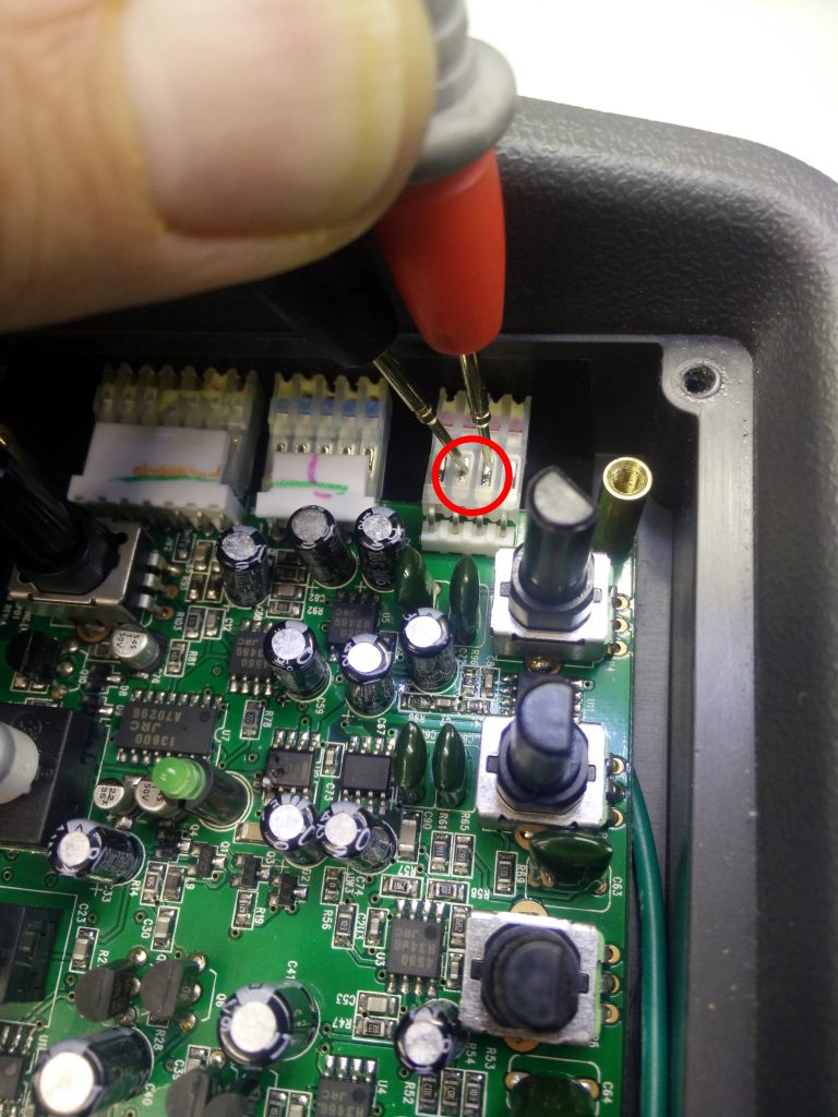
- If you get twice 25V, the input power for the mixing board is OK. We will now proceed checking the on board +15V and -15V voltage regulators.
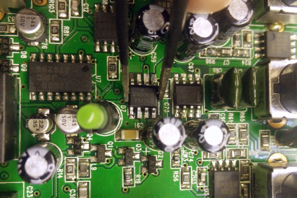
- Measure the voltage over pin 1 (Vout) and pin 5 (GND) of U9 (the eight pin integrated circuit at two o’clock of the green LED. If it is -15V it is OK, if it is less (I measured 0.8V), we will replace this integrated circuit. When looking at the board with the connectors facing upwards (like on the photo), pin 1 is the the top right one and pin 5 is the bottom left one.
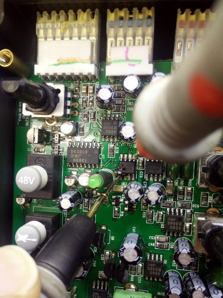
- Measure the voltage over pin 1 (Vout) and pin 6 (GND) of U8. If it is 15V it is OK, if it is less, we will replace this integrated circuit. In my case the voltage was 15V. When looking at the board with the connectors facing upwards (like on the photo), pin 1 is the the top right one and pin 6 is the the second from left on the bottom row of pins.
Parts
Depending on the defective part, you will need to order these replacements:
- MC78L15ACD (U8, +15V 100mA linear voltage regulator, SOIC-8)
- MC79L15ACD (U9, -15V 100mA linear voltage regulator, SOIC-8)
Take note that these components are also available in a TO-92 package (3 leads), make sure you get the SOIC-8 package!
Repair
- Power down the SRM150 with the power switch on the back and unplug the mains lead.
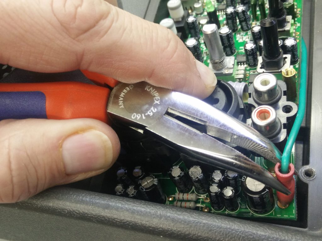
- Unseat the red spade connector of the green ground wire from the circuit board. Wiggle gently to loosen it. Use needle nose pliers to grip the spade connector if needed.
- Lift the lower part of the circuit board up and out of the enclosure.
- Disconnect the three connectors at the top of the board. The board should now be loose and you can remove it completely.
- Remove the defective integrated circuit. As these are surface mount components, this is not easy but not impossible. I normally use a hot air soldering gun for a task like this, but the surrounding electrolytic capacitors make the integrated circuit hard to reach. I decided to perform the operation with a soldering iron: add lots of solder to one row of pins so that all of them are soaked in a liquid solder blob. While heating the blob with your soldering iron, lift that part of the integrated circuit from the board by prying between the integrated circuit and the board with a fine flat screwdriver.
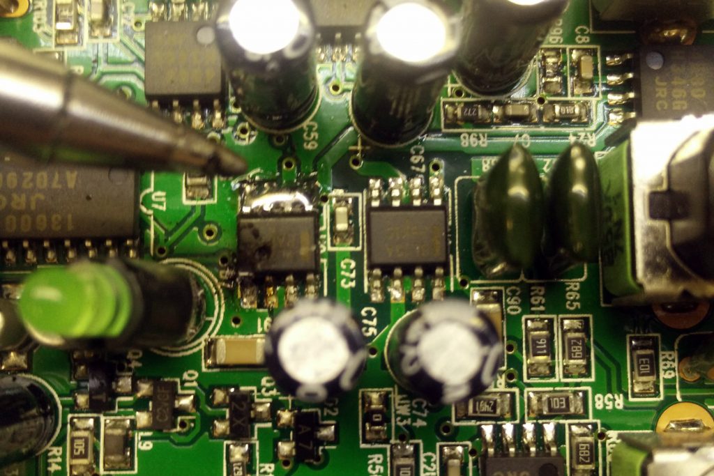
Try so perform this as swift as possible to mitigate overheating of the board, otherwise the copper traces and pads could loosen due to excessive heat. But also be gentle, prying to hard could also lift a solder pad. - Repeat for the row of pins on the other site of the integrated circuit. This should free the defective component from the board. This time you can use tweezers to hold the integrated circuit and lift if from the circuit board.
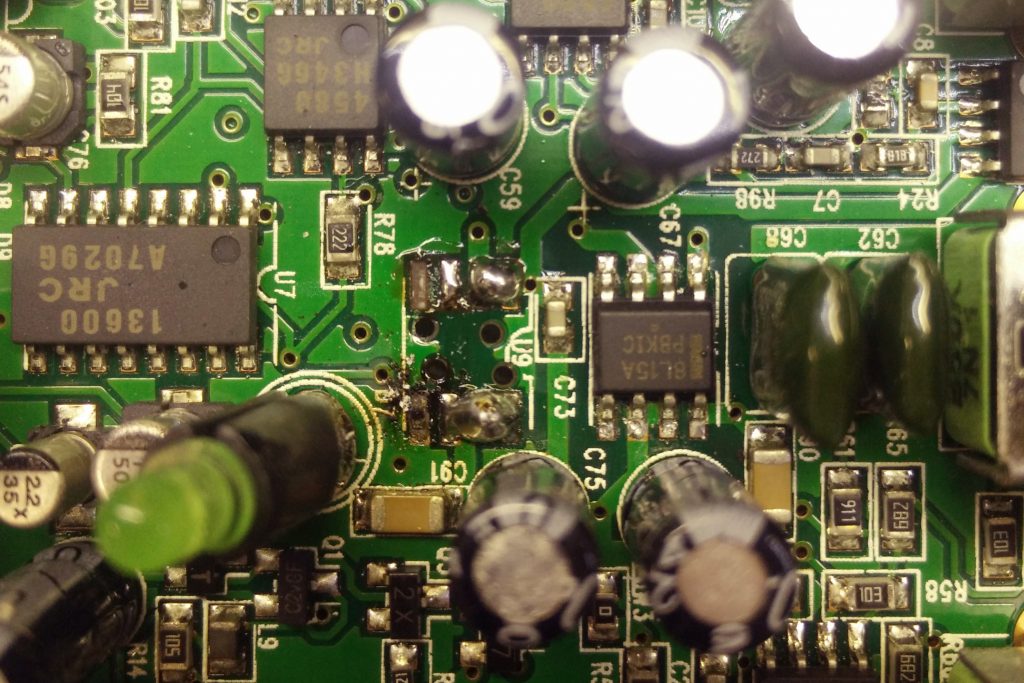
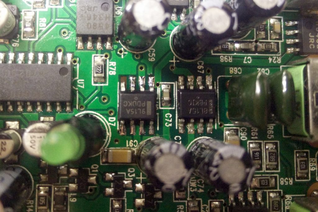
- There is now probably some excess solder on the board. Remove it with desoldering braid. You can see on the photo that I was a bit to harsh and I lifted the pad for pin 4 (top left on the photo). Luckily, this pin is not connected and the pad leads nowhere.
- Add a little bit of solder to one of the corner pads for the integrated circuit. Place the new integrated circuit over it and apply heat with your soldering iron. Reheat the solder joint if necessary to reposition the integrated circuit with the tweezers.
- When positioned correctly, solder the remainder of the pads.
- Check to make sure that there are no solder bridges between the pads.
Make it better
The repair is finished, but this has not resolved the possible root cause of the defect. The SRM 150 Service Bulletin (2008-8-17) has a Rework Procedure for the SRM150 Preamp RevB or earlier. It consists of adding diodes around the +15 vdc and -15 vdc regulators in the preamp of the SRM150. This is a preventative measure to increase the longevity of these regulators.
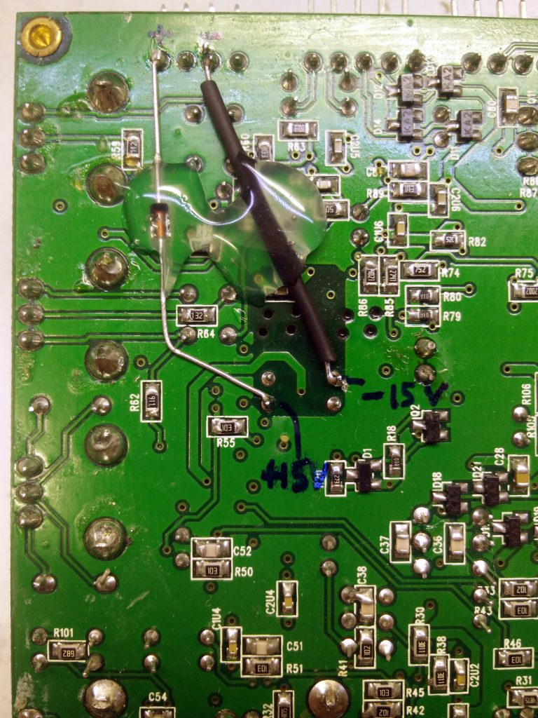
So better to add these two diodes before connecting the PCB again and closing it all up!
What diodes do i need?
You will need two 1N4148 diodes.
Very helpful post. I had two srm 150 units fail in one week and both had virtually the same U9 readings you described. I wanted to do as you recommend and go the extra step to add the 1N4148 diodes but I couldn’t locate the service bulletin you mentioned. Do you have a link to it?
http://service.mackie.com/secure/ServiceLibrary/Mackie/SRM%20Speaker%20Series/SRM150/SERVICE%20BULLETIN%20–%20SRM150%20preamp%20fix.pdf
The link does not seem to exist any longer.
How are the diodes oriented with respect to the “+” and “-” sides of the diode?
The repair tutorial was just what I needed. Clear, concise. Great pictures.
Thanx,
Sal
Nice to hear that. I have fixed the link.
The replacement parts needed does not match the ic chip, was given a 3pin regulator instead. Not the same as pictured, or am I getting it wrong? Pls advice. Thanks
Abdul, please note that a lot of electronic components are available in different packages. You probably got a TO−92 package while you need a SOIC−8 package in the Mackie SRM150.
The manufacturer notes this with a small suffix in the part number: MC78L15ACP (P suffix) for the TO-92 and MC78L15ACDR2G (D suffix) for the SOIC-8.
You can find more info if you look for the data sheet of this part by ON Semiconductor.
THANK YOU THANK YOU. I also had .8 v on my U9, the U8 is good. Thank you again..
This is what I get for back feeding 48V Phantom power into the XLR plug from a different source.
Tom
All done, I also added the 1n4148 switching diodes. Getting the IC off was fun, I floated it, but it still did not want to play nice… thanks a again, saved a bunch.
Nice work! The harder the task the greater is the reward 🙂
I don’t get 25V on the two right pins of J4 but looks ok on the centre pins of J4. Is there a problem with my input to the mixing board and if so do you have any advice.
My symptoms are blue mains light comes on on but no sound, hiss, hum or crackle at all.
You need twice the 25V because the mixing board needs a “dual rail” power supply: negative 25V and positive 25V”. The culprit can be the power supply that feeds the power via the cable to J4, or it can be a short circuit on the mixing board that “drags down” the power rail. TIP: disconnect the cable going to J4 and measure the voltages on the J4 connector again after power off/on. If the voltages are present, then it is a short circuit on the mixing board. If the voltage is missing, it should be the power supply.
Thanks for posting this! I did the repair with MC79L and I did the service bulletin fix with the diodes. I ended up pulling up pads at pins 4 & 8 which luckily are NC on the chip.
Anyway, the amp works fine now. Good as new, maybe better. 0.40 cents and a little time to fix a $300 amp. Nice.
Peter, nice to hear that. Thumbs up for your repair!
Any body has single line diagram fro Mackie SRM 150 ?
I really needs it please
smartbuild168@yahoo.com
Is the covered heat shrink 1n4148 going in the opposite or the same direction as the uncovered. I’m assuming opposite because the polarity is -15v, but wanted to make sure. Btw…thank you very much for this tutorial!!
Check the service bulletin (https://lieven.kks36.be/wp-content/uploads/2018/06/SERVICE-BULLETIN-SRM150-preamp-fix.pdf), it is going in the opposite direction as the uncovered diode.
Hello friend,
I am writing to you from sunny Florida, USA.
Recently, I purchased a Mackie SRM150 , because my friend has his for many years and I really like his.
His amp broke recently, and made the same type of noises that you described.
Since your instructions pictures and explanations were so clear I knew that with your wonderful help I WILL fix it.
So, I went on Ebay and purchased a damaged one ( for $80) , having the same symptoms, betting that I could fix it too.
U9 was not working. I ordered the IC’s and diodes.
The parts just arrived in the mail.
Well, today was the big day.
Your instructions were so clear, almost like making chicken soup out of a clear recipe.
Having never worked with SMD’s it took me a while to extract and replace.
The diodes were easy.
I lucked out and the one unit is done and working.
One more to go.
I can not thank you enough.
may God bless and keep you well and happy.
Another Mackie saved from the dump and you learned SMD! Glad I could help.
Many thanks for this post – I haven’t found much on SRM150 repairs. I’ve had a pair of these for maybe 15 years. Their issues sound related to two of your central issues: considerable hiss/noise from the MAIN volume and LOUD popping. That said, there is speaker output and no pop when powering off. (My workaround for years is simply to adjust volume on the channels and leave the Main pot at 10.) On each unit, input power is okay, and the voltage on both ICs check out okay. I haven’t done the diode upgrade yet but that wouldn’t affect the ongoing problem. Any helpful thoughts? Should the ICs be replaced anyway i light of the hiss/pop problems? With appreciation for any quick thoughts you can share.
I would certainly go for the diode fix described in the service document to protect the +15 and -15 volt regulators. It is an easy fix and less work than replacing the regulators.
Thanks! Will do as I’m sure its worth it. I remain curious though about the fix for the hiss/pop issues with the Main pot as your description of issues tied to the ICs sound precisely like my issue. I appreciate the response! John
Hello John Howland,
It sounds like you a simple problem of a “dirty potentiometer” ( your main volume control).
I would use a contact cleaner ( I use “Deoxit- D5”- for years now).
While at it, I would clean spray ALL the pots – on the mixing board.
Adding the diodes is a MUST.
Good luck
My Mackie SRM 150 suddenly stopped working. When I try to power it up, nothing happens most of the time. I noticed, when I banged the top of the unit, that the blue power light came on and I got sound, then the light went out. Repeated hitting of the unit lit the blue light briefly. I’ve opened it up and plugged and unplugged various connectors but the problem persists. Any suggestions? I’d really like to get this working.
My SRM150 makes no noise, the lights pulsate.. (not sure if they did that when it was functional.) I replaced the board thinking that this would fix it.. but didn’t. Tested speaker stand alone…. that’s fine…
Any idea what could be the problem… not the speaker, not the board!
Hice la reparacion siguendo las instrucciones al píe de la letra, me siento feliz de recuperar mi Mackie SRM 150 que di por perdida, mil gracias por compartir sus conocimientos, bendiciones!
I have 2 SRM150 AMPS not working. One does not power up at all and the other powers on and makes a faint contact pop-pop-pop-pop noise that does not change with volume knob. Any advice?
I suggest you measure the power rails with a multimeter.
Just wonder which Fluke test probes you are using? My stock ones with the 87-5 keep bumping into other components…
Those are not Fluke but cheap $5-ish alternatives with fine tips. Certainly not top noch, but they last a couple of years. Look for “fine multimeter probes” on AliExpress or Amazon.
I have an issue where the power supply is ticking – does anyone have any tips? I have the schematic – but don’t get any -25V is the reference transistor possibly short/broken?
Hello,
Just got done doing this repair on an SRM-150 that I picked up very cheap. Only one regulator was bad (+15). Also did the diode mod. My unit is rev A00, it did not have the ground jumper from the front PCB to ground, I am wondering if I should add it? Thanks for the info.
As the units I repaired were not mine, I can not check what the ground jumper is for. If your unit is working fine I would just leave it like that.
Hallo, ich habe eine Mackie SRM 150 nach der hervorragend guten Beschreibung repariert. Der 79L15 war defekt. Die Box gibt wieder ein gutes Signal über den Lautsprecher ab. Allerdings gibt es an den Volumenreglern bei ca 3 Uhr einen Lautstärkesprung. Kann mir jemand helfen?
My SRM150 turns-on, at full power, all channels sound, but at low volume as if the amplifiers were not working properly. What can I do to fix this?